Passive Notch Filter Schematic
Twin t active notch filter Passive youspice notch The circuit below is an active notch filter with a
Designing Notch Filter Circuits
Is possible compute the bandwidth of a narrowband twin-t passive notch Simple adjustable notch filter circuit diagram Filter notch 60hz hz 60 build
Tl081 tunable notch filter ~ amplifiercircuits.com
Filter notch circuit adjustable diagram simple schematicsSolved passive twin-t notch filter design the basic form of Passive twin-t notch filterDesigning notch filter circuits.
Filter notch twin passive circuit circuitlab description(a) schematic of the ir lna with the third-order passive notch filter Op amp notch filter circuitBand pass and band stop (notch) filter.

Build an adjustable high-frequency notch filter
Filter notch passive schematic lna circuitWiring diagram for passive notch filter for guitar Free project circuit schematic: a twin t passive notch filterFilter notch twin passive bandwidth narrowband compute possible.
(a) schematic of the ir lna with the third-order passive notch filterNotch filter circuit circuits twin schematic designing homemade Notch audio filter build circuit diagramNotch filter (bandstop): what is it? (circuit & design).

Notch variable
Designing notch filter circuitsNotch filter circuit passive band bandstop stop electrical4u transfer function Untitled — build a 60hz notch filterNotch filter passive twin.
Notch filter (bandstop): what is it? (circuit & design)Band stop filter Notch filter twin passive solved basic form answer problem been hasNotch filter circuit band rlc stop electrical4u characteristics transfer function.

Filter notch active circuit help understanding please am
Filter notch band stop passive twin 60 frequencyPassive notch schematic lna Notch filter 60hz analog circuitBand stop filter circuit pass lc notch bandpass circuits filters theory figure characteristics electricalacademia.
Notch filter (bandstop): what is it? (circuit & design)Filter notch circuit twin band basic stop reject filters theory application electrical parallel shown below figure Collection of passive filtersNotch circuits precision incorporates.
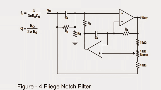
Filter notch circuit op amp diagram values active using component calculations quite easy also
Filter notch twin active band reject factor questions stack qualityLtc6078 60hz notch filter circuit collection Notch active electrical4u transferBuild an audio notch filter 2.
Basic twin-t notch filter circuitVariable notch filter circuit Notch filter example electrical4u transfer function circuitFilter notch tl081 tunable circuit audio frequency band hum circuits narrow gr next.

Notch filter (bandstop): what is it? (circuit & design)
Notch wiring passive database bandpass gyratorNotch frequency edn .
.


(a) Schematic of the IR LNA with the third-order passive notch filter
basic Twin-T Notch filter circuit

Wiring Diagram For Passive Notch Filter For Guitar - Database

Build an Audio notch filter 2 | Electronic Circuit Diagrams & Schematics

Designing Notch Filter Circuits

Simple Adjustable Notch Filter Circuit Diagram | Electronic Circuit